
SFP+ Optical Transceiver,10Gbps 1310nm 10Km
SFP+ Transceiver,10Gbps 1310nm 10Km


SFP+ Transceiver,10Gbps 1310nm 10Km
10Gbps 1310nm SFP+ Transceiver, 10Km
1.Feature
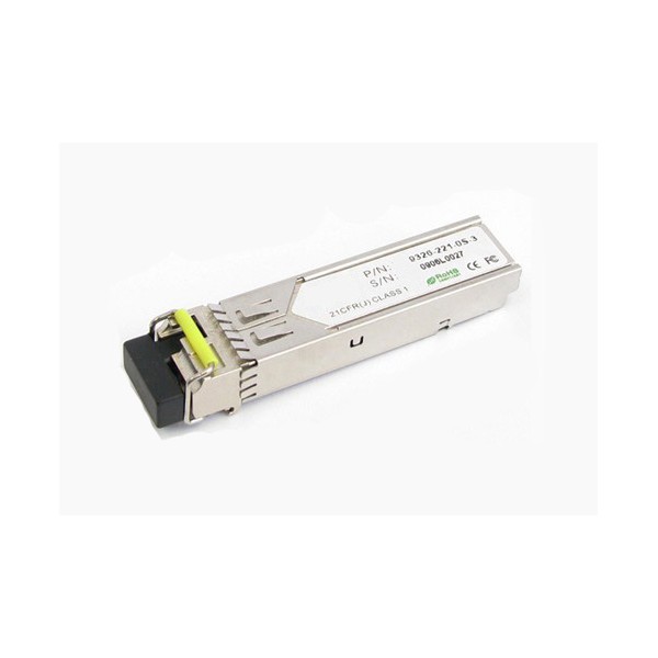
l SFP+ transceiver package with LC connector
l 1310nm DFB Laser and PIN photo detector
l SFP+ transceiver Up to 10km transmission on SMF
l Power dissipation < 1W
l LVPECL compatible data input/output interface
l Low EMI and excellent ESD protection
l laser safety standard IEC-60825 compliant
l Compatible with RoHS
l Compatible with SFF8472
2.Application
l Ethernet
l Fiber Channel
3.Absolute Maximum Ratings
|
Parameter |
Symbol |
Minimum |
Maximum |
Units |
|
Storage Temperature |
Tst |
-40 |
+85 |
°C |
|
Supply Voltage |
Vcc |
0 |
+3.6 |
V |
|
Operating Relative Humidity |
RH |
0 |
85 |
% |
4.Operation Environment
|
Parameter |
Symbol |
Min |
Typical |
Max |
Units |
|
|
Supply Voltage |
Vcc |
3.15 |
|
3.45 |
V |
|
|
Operating Case Temperature |
Commercial |
Tc |
-5 |
|
+70 |
°C |
|
Power Dissipation |
|
|
|
1 |
W |
|
|
Data Rate |
|
|
10.3125 |
|
Gbps |
|
5.Optical Characteristics
(Ambient Operating Temperature -5°C to +70°C, Vcc =3.3 V)
|
Parameter |
Symbol |
Min. |
Typ. |
Max. |
Units |
|
Transmitter Section |
|||||
|
Center Wavelength |
lo |
1290 |
1310 |
1330 |
nm |
|
Side-Mode Suppression Ratio |
SMSR |
35 |
- |
- |
dB |
|
Average Output Power |
Po |
-8 |
- |
+0.5 |
dBm |
|
Extinction Ratio |
Er |
3.5 |
- |
- |
dB |
|
Dispersion Penalty |
|
|
|
3.2 |
dB |
|
Relative Intensity Noise |
RIN12OMA |
|
|
-128 |
dB/Hz |
|
Total jitter |
Tj |
IEEE 802.3ae |
|
||
|
Receiver Section |
|||||
|
Center Wavelength |
lo |
|
1310 |
|
nm |
|
Receiver Sensitivity |
Rsen |
|
|
-12.5 |
dBm |
|
Stressed Sensitivity |
Rsen |
|
|
-10.5 |
dBm |
|
Receiver Overload |
Rov |
0 |
|
|
dBm |
|
Return Loss |
|
12 |
|
|
dB |
|
LOS Assert |
LOSA |
-20 |
|
|
dBm |
|
LOS Dessert |
LOSD |
|
|
-17 |
dBm |
|
LOS Hysteresis |
|
0.5 |
|
4 |
|
6.Electrical Characteristics
(Ambient Operating Temperature -5°C to +70°C, Vcc =3.3 V)
|
Parameter |
Symbol |
Min. |
Typ. |
Max. |
unit |
|
|
Transmitter Section |
||||||
|
Input Differential Impendence
|
Zin |
90 |
100 |
110 |
Ohm |
|
|
Data Input Swing Differential |
Vin |
180 |
|
700 |
mV |
|
|
TX Disable |
Disable |
|
2.0 |
|
Vcc |
V |
|
Enable |
|
0 |
|
0.8 |
V |
|
|
TX Fault |
Assert |
|
2.0 |
|
Vcc |
V |
|
Deassert |
|
0 |
|
0.8 |
V |
|
|
Receiver Section |
||||||
|
Output differential impendence |
Zout |
|
100 |
|
Ohm |
|
|
Data output Swing Differential |
Vout |
300 |
|
800 |
mV |
|
|
Rx_LOS |
Assert |
|
2.0 |
|
Vcc |
V |
|
Deassert |
|
0 |
|
0.8 |
V |
|
7.Diagnostics
|
Parameter |
Range |
Accuracy |
Unit |
Calibration |
|
Temperature |
-10 ~ 75 |
±3 |
ºC |
Internal |
|
Voltage |
0 ~ VCC |
0.1 |
V |
Internal |
|
Bias Current |
0 ~ 100 |
0.5 |
mA |
Internal |
|
Tx Power |
-8 ~ 1 |
±1 |
dBm |
Internal |
|
Rx Power |
-18 ~ 0 |
±1 |
dBm |
Internal |
8.EEPROM INFORMATION(A0)
|
Addr |
Field Size (Bytes) |
Name of Field |
HEX |
Description |
|
0 |
1 |
Identifier |
03 |
SFP |
|
1 |
1 |
Ext. Identifier |
04 |
MOD4 |
|
2 |
1 |
Connector |
07 |
LC |
|
3-10 |
8 |
Transceiver |
10 00 00 00 00 00 00 00 |
Transmitter Code |
|
11 |
1 |
Encoding |
06 |
64B66B |
|
12 |
1 |
BR, nominal |
67 |
10000M bps |
|
13 |
1 |
Reserved |
00 |
|
|
14 |
1 |
Length (9um)-km |
0A |
|
|
15 |
1 |
Length (9um) |
00 |
|
|
16 |
1 |
Length (50um) |
00 |
|
|
17 |
1 |
Length (62.5um) |
00 |
|
|
18 |
1 |
Length (copper) |
00 |
|
|
19 |
1 |
Reserved |
00 |
|
|
20-35 |
16 |
Vendor name |
57 49 4E 54 4F 50 20 20 20 20 20 20 20 20 20 20 |
|
|
36 |
1 |
Reserved |
00 |
|
|
37-39 |
3 |
Vendor OUI |
00 00 00 |
|
|
40-55 |
16 |
Vendor PN |
xx xx xx xx xx xx xx xx xx xx xx xx xx xx xx xx |
ASC II |
|
56-59 |
4 |
Vendor rev |
31 2E 30 20 |
V1.0 |
|
60-61 |
2 |
Wavelength |
05 1E |
1310nm |
|
62 |
1 |
Reserved |
00 |
|
|
63 |
1 |
CC BASE |
XX |
Check sum of byte 0~62 |
|
64-65 |
2 |
Options |
00 1A |
LOS, TX_DISABLE, TX_FAULT |
|
66 |
1 |
BR, max |
00 |
|
|
67 |
1 |
BR, min |
00 |
|
|
68-83 |
16 |
Vendor SN |
00 00 00 00 00 00 00 00 00 00 00 00 00 00 00 00 |
Unspecified |
|
84-91 |
8 |
Vendor date code |
XX XX XX 20 |
Year, Month, Day |
|
92-94 |
3 |
Reserved |
00 |
|
|
95 |
1 |
CC_EXT |
XX |
Check sum of byte 64~94 |
|
96-255 |
160 |
Vendor specific |
|
|
9.Pin Description
|
Pins |
Name |
Discription |
NOTE |
|
1 |
VeeT |
Transmitter Ground |
|
|
2 |
Tx Fault |
Transmitter Fault Indication |
1 |
|
3 |
Tx Disable |
Transmitter Disable |
2 |
|
4 |
MOD DEF2 |
Module Definition 2 |
3 |
|
5 |
MOD DEF1 |
Module Definition 1 |
3 |
|
6 |
MOD DEF0 |
Module Definition 0 |
3 |
|
7 |
RS0 |
Not Connected |
|
|
8 |
LOS |
Loss of Signal |
4 |
|
9 |
RS1 |
Not Connected |
|
|
10 |
VeeR |
Receiver Ground |
|
|
11 |
VeeR |
Receiver Ground |
|
|
12 |
RD- |
Inv. Received Data Output |
5 |
|
13 |
RD+ |
IReceived Data Output |
5 |
|
14 |
VeeR |
Receiver Ground |
|
|
15 |
VccR |
Receiver Power |
|
|
16 |
VccT |
Transmitter Power |
|
|
17 |
VeeT |
Transmitter Ground |
|
|
18 |
TD+ |
Transmit Data Input |
6 |
|
19 |
TD- |
Inv. Transmit Data Input |
6 |
|
20 |
VeeT |
Transmitter Ground |
|
9.Pin Description